Saturday, March 31, 2018

Arcade Box of Old

Intro
This is a project I worked on in my free time during my freshman year of university back in the 2015-2016 school year. I remember I saw someone create this arcade control box which housed a Raspberry Pi, and ran a video game emulator. The box then connected to a monitor and you could play with it. I believe I also saw kits where you could pay for the materials and such and follow simple instructions to make it. However, I wanted to use the skills I had just learned that Fall in my ENGR 101 class, and make use of the facilities I now had access to.

Software
While I was researching, I found the emulator that ran on the RPi: RetroPie. All I had to do was install it onto a micro SD card like I would an OS, and it would work. Later, I found out that I would need to install some sort of utility from an Adafruit guide that I was using to help. The utility made it so that the GPIO pins on the RPi would be read as certain keyboard keys. That way, RetroPie could be configured to use the GPIO pins as controls.

Hardware
I first bought an arcade joystick, and 4 coloured arcade buttons from Adafruit, and researched into how to connect it to the RPi (RPi 2, model B.) The wiring was pretty straight forward: each direction from the joystick and each button connected to a different GPIO pin. Furthermore, I later used 2 smaller red momentary switches as a "start" and "select" button wired in the same manner.

The Journey
Once I had the main buttons and the joystick, I remember I hastily wanted to put it all together, but I hadn't created an actual "box" yet. Suddenly, I had one of my more memorable, and possibly even the first, engineering "a-ha!" moment.

Arcade Box Mk. I
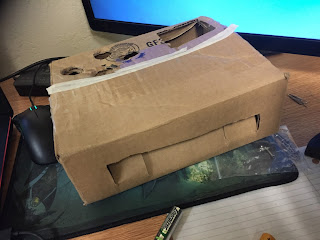
I grabbed a nearby box, and crudely cut holes that would snugly hold the 4 buttons and the joystick, and a hole in the side to be able to externally wire the buttons to GPIO pins. If you look at the breadboard closely, I used 2 breadboard sized momentary buttons as the "start" and "select" buttons. It was a very momentous occasion for me. Here are some more photos I have of back then:
 
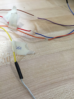
Picture I took to admire my soldering


Couple of pictures of just the box

I realized that doing things like making the arcade box was what I wanted to do: start with an idea, try to make it, and learn along the way (basically what engineering is.) Although functioning, I wanted this all to look and feel better.

In my ENGR 101 class, we were introduced to Solidworks, a 3D modeling software that we could use to design something that we want to build, and then use it with a laser cutter that would cut out our design from a piece of wood. So, since this was free for me, I used it.
Laser cut box before assembly

Laser cut box after assembly

In the latter picture, you can see no "start" or "select" button yet, and that the joystick is actually fitted with screws into the box, it's simply taped to the box. The next couple of photos are ones that I have taken today (March 31, 2018) of the last model of the box I had made.

 Top View (can see 'start' and 'select' buttons in center)

Inside View

Side View (can see latch, and opening for RPi's HDMI, USB, etc.)

Front Panel

Along the years, I have lost the door that is supposed to be the wall to the left of the joystick, but it was always a bit rickety anyways. If you look at the "inside view", you can see a tiny screw and nut at the bottom left, near the RPi opening. I had 2 diagonally placed holes so I could fix the naked RPi board into the box. Also, I made the 4 arcade buttons the same colour and layout as that of Nintendo's Famicon controller as a bit of an easter egg.

Conclusion
The arcade box basically opened my eyes as to what I could now do with the resources given to me, and all that's needed is my own drive to create. This box was dated April 8, 2016, and we're now coming up on 2 years since I've made it. 

I still would like to revisit my old files of the 3D model of the box and fix the joystick as it still is basically being held together with tape. The joystick can be sort of unscrewed with its metal plate so that only the "joystick" bit will actually be external to the box, and for some reason, I could never get the measurements right or something. The holes for the screws were too wide at one point, and in this one the hole is like "too big" for the joystick. It was weird, and I'd like to revisit it so everything looks nice. Also, the holes for the buttons were too tight, and the bits of plastic that made the buttons secure once fitted into the rigid holes broke off, so they are currently being held in place by blue sticky tack: my go-to adhesive for things like this.

This first, self-driven project set off, as corny as it sounds, a sort of spark within me. It started this attitude I began to develop of looking at things I could buy, but asking myself, "Why don't I just make it?" 

References
Adafruit guide (contains utility used for GPIO pins)

March 31, 2018 Update

It has been basically 3 months since my last update of any type. This semester has been pretty rough for my mental; it hasn't been good. However, as I type now at the end of Spring Break, I find new strength and a drive to get back to business. I had an unfinished post about the LED hat from back in December because I remember I hastily finished the thing just in time for me to unveil it at a Theta Tau event. Speaking of, I am now the Treasurer for our fraternity. It hasn't been too crazy, but like many things, I want to make something better, greater, and over the top that will continue past my life as a student here at USD.

Dreams aside, I have to start applying for internships even though it's a bit late at this point (whoops). I was updating my LinkedIn profile and was filling in my projects section (as that is what I have going for me at this jobless point.) There, I saw I could put a link to these projects and decided to see if I could scrounge up the projects I have with me and archive them for future employers to briefly look over (so they can see I'm not a total potato) and for me to see, and revisit if I ever get the feeling to.

School work is continuing to be quite heavy this semester, so it looks like I'll have to self-discipline myself so I have time to do things that are actually productive in some sense and isn't just coming home to mindlessly browse Twitter or play games (especially since most of my friends are busy now.)

I can do it, just gotta work for it.

Tl;dr

  • I'm back again (hopefully)
  • Busy with school, don't know how much time I'll have to create a new project this semester
  • Applying for internships this Summer (please give me one)
  • To make myself look cooler, the next few upcoming posts will be archiving past projects

Sunday, December 3, 2017

LED Hat: A Theta Tau Christmas Intro

I'm a bit late in making a post about this, but a dude's gotta do what he gotta do.

I recently purchased a "Santa dad hat" online since I've been recently been wearing dad hats with varying styles such as a Mario, Luigi, and Wario dad hats. So, being a Christmas season lover, I decided to google "Santa dad hat" and found exactly what I had envisioned. After a week my baby came in and it was everything I asked for; truly Christmas came early (it came in November, before American Thanksgiving had even passed). 
Pictured above: The Santa Dad Hat

After sometime, like a mad genius, I decided that this was not enough. I had to be extra. I wanted to somehow attach LED's so I can have the Greek letters "Theta Tau", my fraternity, on the front. It was impulsive, and I only have <3 weeks left to complete it, but God as my witness it shall be done.

Some design considerations
  • Regular, single coloured LED's or something akin to Adafruit's Neopixels?
    • How would the wiring be done in either case
    • If using neopixels, how big should I make the matrix
  • Use what micro controller?
  • Control it wirelessly?
  • Where would the micro controller be physically?
  • Power source?
Second design consideration: What Micro Controller
I had gone through a lot of thinking over the first and third points. For the second point, I knew that if I used Adafruit's Feather line of micro controllers, I could easily swap out a basic board, the 32u4 Adalogger, for one with bluetooth capability, the 32u4 Bluefruit LE (both of which I already own), with some simple addition of code.

First design consideration: LED Type
If I used, say, a bunch of regular looking LED's that were yellow either by the type of material made, or by some different coloured plastic housing, I could easily, but tediously, poke the leads of the LED's into the hat, in the pattern I wanted, and solder the leads in parallel. That way, I could program some different functions of blinking, fading in and out, etc. with it. The issue is that it would only be a niche image, and if I wanted to do something similar, but with some other image, I would have to desolder the existing design, and solder the new one; very tedious and time consuming. 

If I used neopixels, I could use any design I want, anytime, for basically eternity. I could also make it display more patterns such as a side to side scrolling image.The issue I was mainly concerned with was the coding. It has been a while since I've even touched some Arduino type micro controller, let alone a Raspberry Pi for the laptop project. Also, attaching the strips to the hat might be an issue since I may want to remove the strips in the future and salvage the hat. The size of the matrix would have to depend on the surface area of the hat that is viewable from the front.

Third design consideration: Wireless Capability
If I choose not to use wireless, I would need to somehow create an opening in the hat to allow access for switches somewhere. I'd rather keep the holes I make in this hat to a minimum. If I used bluetooth, I'd need to figure out what code I need to use, which is more complicated than say, using some makeshift breadboard setup and basically sticking it to the side of the hat.

Fourth design consideration: Micro Controller Location
Also something that was almost decided immediately, the hat has a lot of room above where my head is (space is towards the cone). I can simply stick it inside somewhere in there and/or rest it on my head. I'm not going for comfort, but function, ultimately.

Fifth design consideration: Power Source
More of a formality of documentation in writing this down. I know I want to be portable, so the decision to go with either a li-po battery or my portable charger was basically instant rather than carrying around a wall adapter and using that. Also, the battery would also sit inside the hat somehow. I'll test out how both feel in the hat later on, but right now, a portable power source is what I'll ultimately be using.

I decided on using bluetooth, and the neopixels. Though the more complicated combination, I figure the functionality will be infinitely more useful and cool looking.

Keeping this record of what I'm doing takes a lot more time than I thought it would since I've been way more into actually building the darn thing. I don't want to do thing project and then write a final report since I guarantee that me later won't have the thoughts as the me who is currently making the thing. Also, this way I can make record of any failures in real-time. To  compensate (kinda), I've been keeping a notebook of brief and will try to show some of the relevant pages so you can see my thought process. 

Alright, let's get 'er done.

P.S. An idea for use after Christmas: some sort of Harry Potter sorting hat. It'll choose a random hat whenever I send an input and display one of the 4 Hogwarts houses. That'll get me some street cred.

Thursday, November 30, 2017

Makeshift Laptop: The Prequel

I just received what I had thought to be all the parts I needed for this small laptop I wanted to make using the Raspberry Pi, but the screen I got is not compatible with the 40 pin tft to hdmi converter from Adafruit (TFP401) as one component on the board was burning hot to the touch. I have now ordered a 7" tft screen from Adafruit, which is sure to work with the chip, and I can begin construction of the laptop.

Quick list of parts I originally planned on using:

  1. Raspberry Pi 3 Model B (for its built in wi-fi and bluetooth)
  2. Adafruit TFP401 converter
  3. Rii Mini X1 bluetooth keyboard and mouse (all on same board)
  4. Anker Astro E1 5200 maH portable charger (power source)
  5. 10.1" Laptop Screen Part # LED-1024-600-G-40-10.1-8
While I wait on the new screen to come in, I am setting up a new micro SD card for the laptop and doing the necessary changes to some files so that I can connect the Pi to my school's "eduroam" wi-fi network.

Credit to user "Sruc" on this thread who posted the solution to connecting to eduroam.

Bit of an aside, but I remember encountering this problem sometime during the latter half of freshman year and searching for this solution in the past. However, I've been not so diligent in trying to keep up making some sort of project every semester that most of my Raspberry Pi skills are quite rusty. Maybe I'll open up my notebook from my engineering programming class from that time for a refresher.


Tuesday, November 28, 2017

November 2017 Update: The return that will hopefully work

Whew 4 months sure pass by quickly. As an update, my Summer was very unproductive, but I did manage to get myself a soldering kit which was pretty cool. I kept myself busy by going to the dollar store, finding cheap electronics and try to dissect the circuits inside them. There was this simple PCB I found in a $2 lawn lamp. It had a solar panel to charge a small battery of some sort. It also had a on/off switch if you wanted to enable the functionality of the lamp; turn off the LED during daytime and charge the battery, and then turn on the LED at nighttime. 

Long story short, I couldn't figure out the circuit diagram for it because there was a black epoxy covering what I suspect to be some sort of transistor (a component I had not been taught about before).

I also found a cheap light that would turn on if it detected motion. I only took it apart once and quickly scanned its components. If I recall correctly, the circuit used some sort of photo resistor to detect motion. 

Apart from these small electronics, did not really do too much. Now, I'm almost done the first semester of my Junior year and have a great deal of projects I want to do, or at the very least attempt.

A tentative list of such projects in no particular order:
  • Albert's Gift (fix 3D printed enclosure)
  • Arcade Box (Redo laser cut wooden enclosure into something that works)
  • Makeshift Raspberry Pi (I ordered a laptop screen and various parts to make a cardboard laptop out of and hopefully I can laser cut/3D print a good enclosure)
  • Amazon Echo Stuff / IoT
  • The various Adaboxes to do
Hopefully I can knock at least 3 of these before the school year ends next May. I got big dreams, but only by actually doing something can they come to fruition. Let's also hope I stick to this work ethic.

Thursday, June 15, 2017

Albert's Gift: Part 2

Damn I suck at keeping up with new hobbies. I've been busy being lazy keeping up to date on this blog, but I'm on summer vacation right now with no job and continuing to be a lazy guy. However, I have been slowly but surely working on Albert's gift. I believe the last post talked about the 3D enclosure for the circuitry. I tried printing out the enclosure straight from the files the Adafruit tutorial gave, but something wonky happened and the walls of the enclosure was too small for the top and bottom pieces to fit on. Not being well versed in 3D printing and its software, I attempted to simply scale the wall piece a little bit to allow for enough room, but the end result is some thinly printed plastic that is now a bit too loose.


Shown above is the side of the enclosure that allows the arduino to be plugged with either a micro-USB cable or a 5V DC supply. I didn't have enough time to fix the design and print a better side, but it holds well enough. It just looks like a termite mound.

After the 3D printing step was done, I had to solder on a few wires to the Adafruit Trellis board so it can connect with the arduino inside. But before I go on, I want to talk about a problem I encountered yesterday when I was working on the code.

I originally was using an arduino R3 as the microprocessor. As I was attempting to write code to simulate one of the buttons typing in a capital "A", I learned that the R3 was not able to use the "Keyboard" library due to its installed microcontroller. Believing that I could surely pull it off anyways through some sort of manual update of the firmware that would disregard this restriction, I did a quick Google search and found that it was possible, but I would have to solder on a 10K ohm resistor to a couple of pins on the bottom of the R3. I figured that since I don't have a soldering kit and the 10K ohm resistor attached to the bottom would make the R3 too big for the enclosure, I simply went out and bought an arduino Leonardo. The microprocessor on this arduino was actually able to naturally use the "Keyboard" library and allow for what I wanted.

Back to the soldering of the Trellis board, below you can see a quick picture I just took of the circuitry between the Trellis board and the arduino Leonardo.

Furthermore, I soldered on 16 LEDs to each of the 16 button locations so when one is pressed, it would light up until released.

With the hardware complete, I now move on to the coding of this project. So far, I have been able to simulate a capital "A" when pressing whatever button I code it to be (I made it the button labeled "1" on the Trellis board). Preparing myself for coding all buttons to simulate a keystroke of the keyboard, I am attempting to make a switch statement. The code is written so that it goes through each button (1-16 on the Trellis, but indexed 0-15 in the code) in ascending order, checking which button has just been pressed. Whatever button it's checking is saved into the aptly labeled "i" integer which will be the expression used in the switch statement. I will have 16 cases for each number in the closed set   [0, 15] and program them to simulate a single letter of the alphabet from A to P, which should be the first 16 letters.

I will test with only the first 2 buttons to see if this switch statement will work as intended, and later code in the LED functionality. 

Fingers crossed.

Tuesday, March 21, 2017

Albert's Gift: The Beginning

I got a friend named Albert. He's been my best friend since middle school. Without going into details, his family has been hit with a bit of a financial situation. We talked about it in private and stuff, and immediately, I tried going through as many money making schemes to fund raise for him. I've never felt more helpless before.

So here's what I decided to do. I'm gonna make him something. Something completely unnecessary, but something that I hope will mean something to him. We're both men of few words, so hopefully this will communicate something I can't say.

We're both really into an MMO called Final Fantasy XIV (14). In MMO's, players usually need a plethora of keybinds for their skills. There's only so many keys a left hand can reach, and so many combinations (ie 4 or shift+4 or ctrl+4 for 3 different keybinds) it can make. So what game peripheral companies have made are ergonomic "keypads" that fit naturally to the left hand, and basically have ~16 keys, fully programmable to be any kind of keystroke(s). These usually run $60 USD which is like $10 billion CDN. So I'm gonna make Albert a small keypad.

The keypad will be a 4x4 grid and made from the Adafruit Trellis; a PCB I've ordered that's specifically meant for this kind of use. It'll be used with an Arduino Uno inside a 3D printed enclosure and act as a 16 key, keypad.

The buttons aren't any sort of mechanical switch; it's membrane. Membrane sucks dick. Buuuuttt it reduces cost and it'll make my initial make of this thing easier. I have all the materials save for the 3D enclosure from which the plans are taken from a "learn" article on Adafruit's website.

The issues I foresee is reprogramming the buttons to whatever Albert's specific keybinds are. I'm planning on getting this done before I next go back home to Canada, so I can be with him and set it up at his house (and also have a full bromo talk with him or some shit). Also, I don't know how the code works yet lol. I've taken a look at the trellis tutorial, but I'm still not sure what is going on.

The first step is getting the 3D parts I guess. In the meantime I'll attempt to work out the code that is supposed to work with the Arduino IDE, but it's been a while since I last coded for "real". I'm also busy trying to figure out all my transfer stuff which is all a pain, but Albert is worth it.

Really hope he doesn't see anything here until I finish this. More to come soon, maybe. Hopefully a week at most.